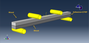
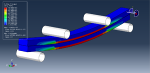
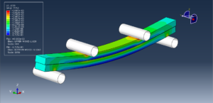
In this tutorial the Simulation Wood-Glue-CFRP beam under dynamic four points bending test in Abaqus has been investigated. The wood beam are modeled as three dimensional solid part, the adhesive parts are modeled as three-dimensional solid parts, the CFRP also si solid and the the roller are modeled as rigid shell parts. You can see a figure of the assembled parts below
Structural elements made of combiningwoodwith FRP composites are the current research topic undertaken by many scientists. There are several known ideas of strengthening and reinforcing solid and glue laminated timber. For strengthening solid wood, the first method is gluing strips to the bottom of a girder on the entire cross-section width. The second method is gluing strips to the bottom of the girder, but not on the entire cross-section width. Another method is to fold the composite onto the vertical planes of the girders. The last method is cutting a cross-section and gluing a plate into the prepared incision
All deformable parts like wood beam, CFRP, and adhesives are modeled as three-dimensional solid parts. Material of wood and CFRP tapes is Elastic/Engineering Constants and Plastic/Isotropic with Potential. Adding Potential option enables to define strength in respective directions using Hill’s function coefficients. Material of adhesive layers is Elastic/Traction and Quads Damage. The described example assumes properties for polyurethane (PUR) glue
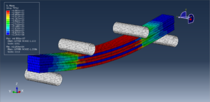
Both static general and dynamic explicit step can be selected, to decrease the time of the simulation, dynamic explicit step with mass scale is considered. The tie or ideal contact is assume between CFRP-adhesive, and Wood-adhesive. The surface to surface contact with contact property is selected to define the contacts among the rigid bodeis with wood beams. The proper boundary conditino and load is assigned to the rigid parts. The mesh should be fine to obtaine the correct results
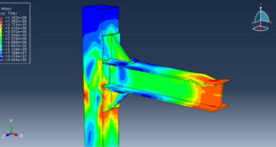
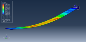
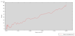
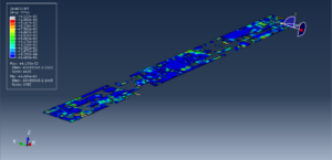
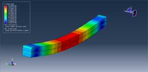
After the simulation, all results such as stress, strain, damage, and force-displacement diagram is avaiable. You can see some figure for the results below

You can provide CAE ,INP,and English video files of this simulation here. The cost of these files is Twenty-six Euros. you can click on the bellow bottom to beginning process
You can purchase the tutorial through a PayPal account, a Visa, or a Master card, just before payment,send me an email to this address: karampourp@gmail.com