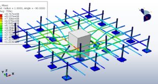
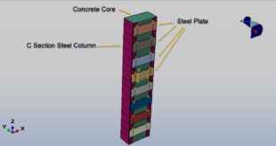
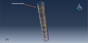
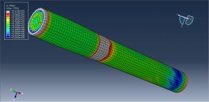
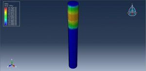
In this tutorial, the Simulation axial compression of the Ultra-High-Performance Fiber Reinforced Concrete Column in Abaqus has been investigated. The UHPFRC column is modeled as a three-dimensional solid part with a circular form. The bars or beams embedded inside the concrete column are modeled as three-dimensional wire parts. Two rigid bodies are used as a supporter and force body. You can see some figures of the assembled parts at below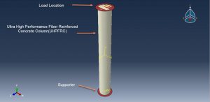
Extensive research and development efforts, over the past three decades, to improve properties of concrete have led to the emergence of ultra-high performance concrete(UHPC). UHPCpossessesveryhighcompressivestrength, good tensile strength, enhanced toughness, and durability properties. However one of the main drawbacks of UHPC is its brittleness property. To overcome the brittleness of UHPC, fibers are often added to UHPC and this type of concrete is referred to as an ultra-high performance fiber reinforced concrete(UHPFRC). Addition of fibers to UHPC can significantly improve its ductility, fracture toughness, and energy absorption capacity
A damage based concrete plasticity model, available in ABAQUS, is utilized to capture the nonlinear material behavior of UHPFRC. The Concrete Damage Plasticity model(CDP)is based on the theory of plastic flow. The CDP plasticity model is used for the UHPFRC column and the material data for it is extracted from the reference paper. The steel material with elastic-plastic behavior is used for the part of the beam. The general static step is used to model static compression. The general contact algorithm with contact property is used for all contacts domain. The beams are embedded inside the concrete host. The fixed boundary condition is assigned to the bottom rigid body and displacement boundary to apply compression load to the top rigid body is applied. The mesh should be fine to achieve good results
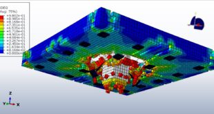
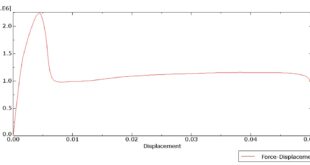
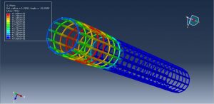
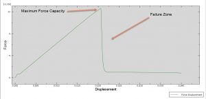
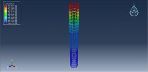
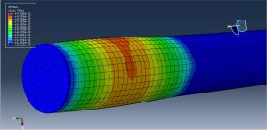
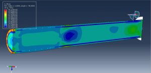
After the simulation all results such as stress, strain, displacement, and force-displacement diagram are obtainable. Base on the force-displacement diagram the maximum force capacity and failure zone can be specified. You can see some figures for the results below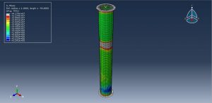
You can provide CAE ,INP,and English video files of this simulation here. The cost of these files is Twenty-Six Euros. you can click on the bellow bottom to beginning process
You can purchase the tutorial through a PayPal account, a Visa, or a Master card, just before payment,send me an email to this address: karampourp@gmail.com