In this tutorial, the Numerical analysis of tilted angle shear connectors in steel-concrete composite systems in Abaqus has been investigated. The concrete block is modeled as a three-dimensional solid part. The steel beam and steel angle connector are modeled as three-dimensional solid parts. Two rigid bodies are used as boundary location and hydraulic jack. You can see a figure of the assembled parts below 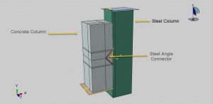
Shear connectors are an important part of the design of composite beams. An effective connector provides for adequate shear strength for full composite action between the steel beam and concrete. In addition, its ductile behavior can alarm imminent collapse. The ease of construction and economical aspects are also of concern. The search for new connectors that satisfy these criteria continues and innovative developments appear routinely. Nowadays, several types of connectors are available such as stud, Perfobond, channel, and angle connectors. The angle shear connector provides for shear strength through one leg and resistance against uplift through another leg that acts as a flange
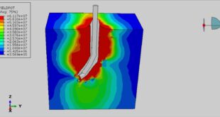
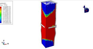
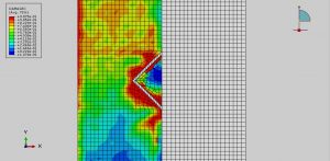
The Concrete Damaged Plasticity is used to define concrete block behavior. The model is a continuum, plasticity-based, damage model for concrete. It assumes that the main two failure mechanisms are tensile cracking and compressive crushing of the concrete material. The elastic-plastic material model is selected for the steel shear angle connector and beam. The dynamic explicit step instead of the general static one is selected to avoid not convergence. The surface-to-surface contact is used to define contact between steel beam and concrete. The perfect contact is assumed between concrete and shear angle connectors. The fixed boundary is assigned to the bottom rigid body and displacement as the load to the top rigid body. The symmetry boundaries are applied to the symmetry zones. The mesh should be fine to obtain more accurate results
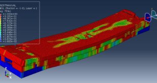
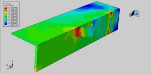
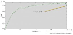
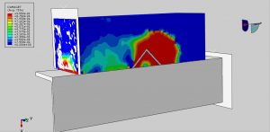
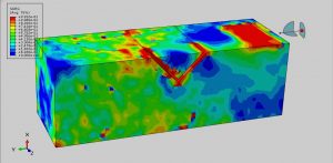
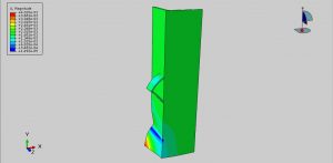
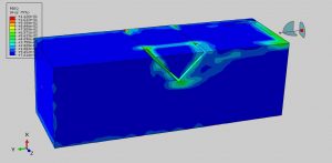
After the simulation all results such as stress, strain, tensile and compressive damage, force-displacement diagram, and… are available. You can see some figures for the results below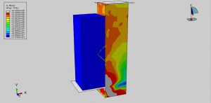
You can provide CAE, INP, and English video files of this simulation here. The cost of these files is Twenty-Six Euros. you can click on the bellow bottom to beginning the process
You can purchase the tutorial through a PayPal account, a Visa, or a Master card, just before payment, send me an email to this address: karampourp@gmail.com